Skip to content

Measured on a real VNA.
Compared against the RayRF prediction.

We measured 9 real structures on a calibrated LiteVNA64 and compared them to the RayRF simulation results. RayRF shows excellent frequency accuracy with a converged mesh, and generally predicts a less lossy depth than reality, which is consistent with solver idealization of real-world material properties.

Frequency accuracy
< 1%
Worst-case frequency error across all resonances on the structures below (Very High auto quality setting).
Measured
9structures
Eight patch antennas and an interdigital bandpass filter on the ZYF 300CA-C substrate (0.76 mm PTFE, Dk 2.94, Df 0.0016).

Per-DUT comparison

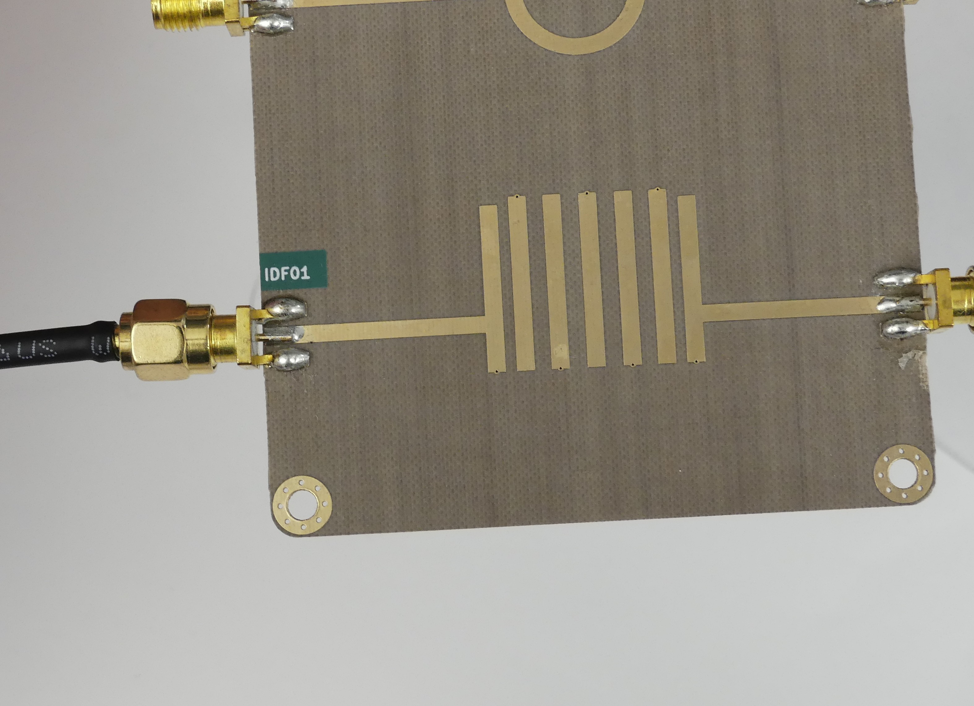
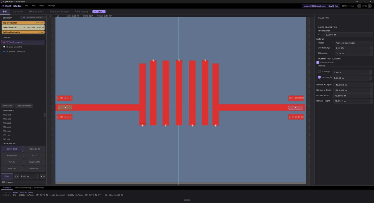
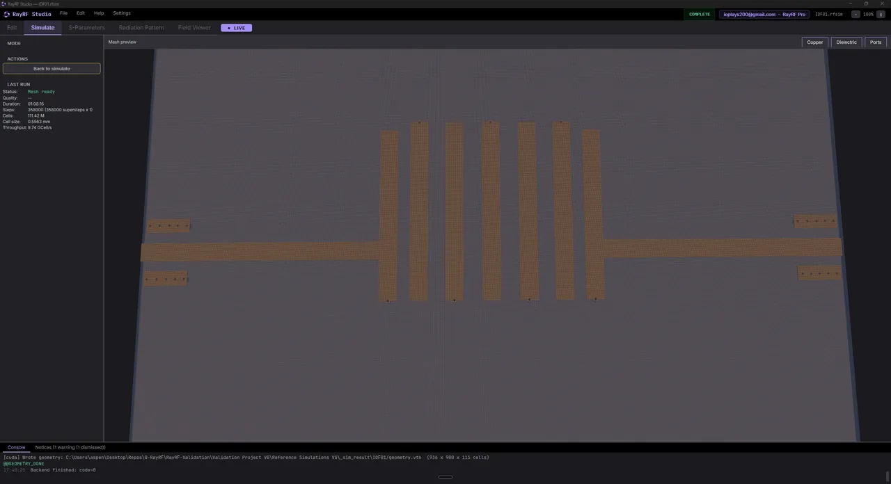
[IDF01]Interdigital Bandpass Filter (~2.4 GHz)

Four-pole interdigital bandpass filter. Individual pole frequencies match within 1% across the band.

ctrl/shift+scroll: zoom  |  left or right drag: pan  |  double-click: reset
scroll to load
RayRF Studio
RayRF Studio
Mesh preview
Mesh preview
Hardware
Hardware

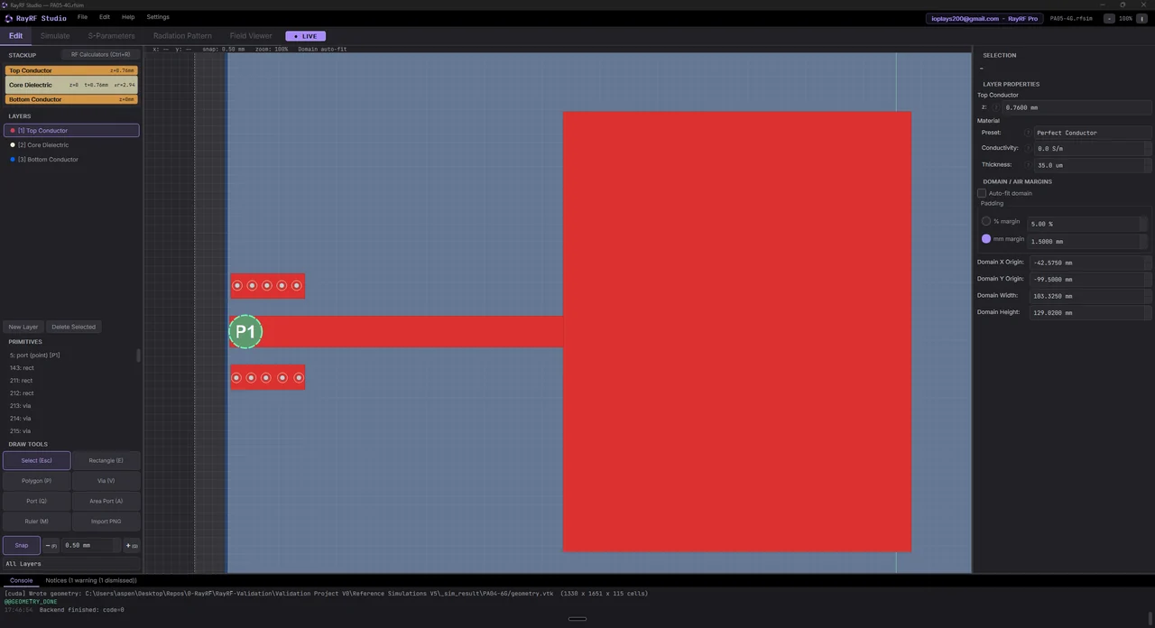
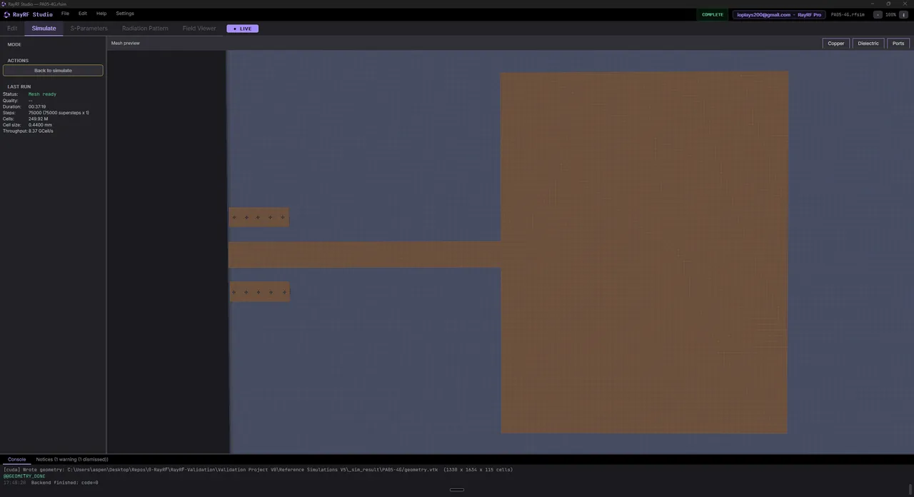
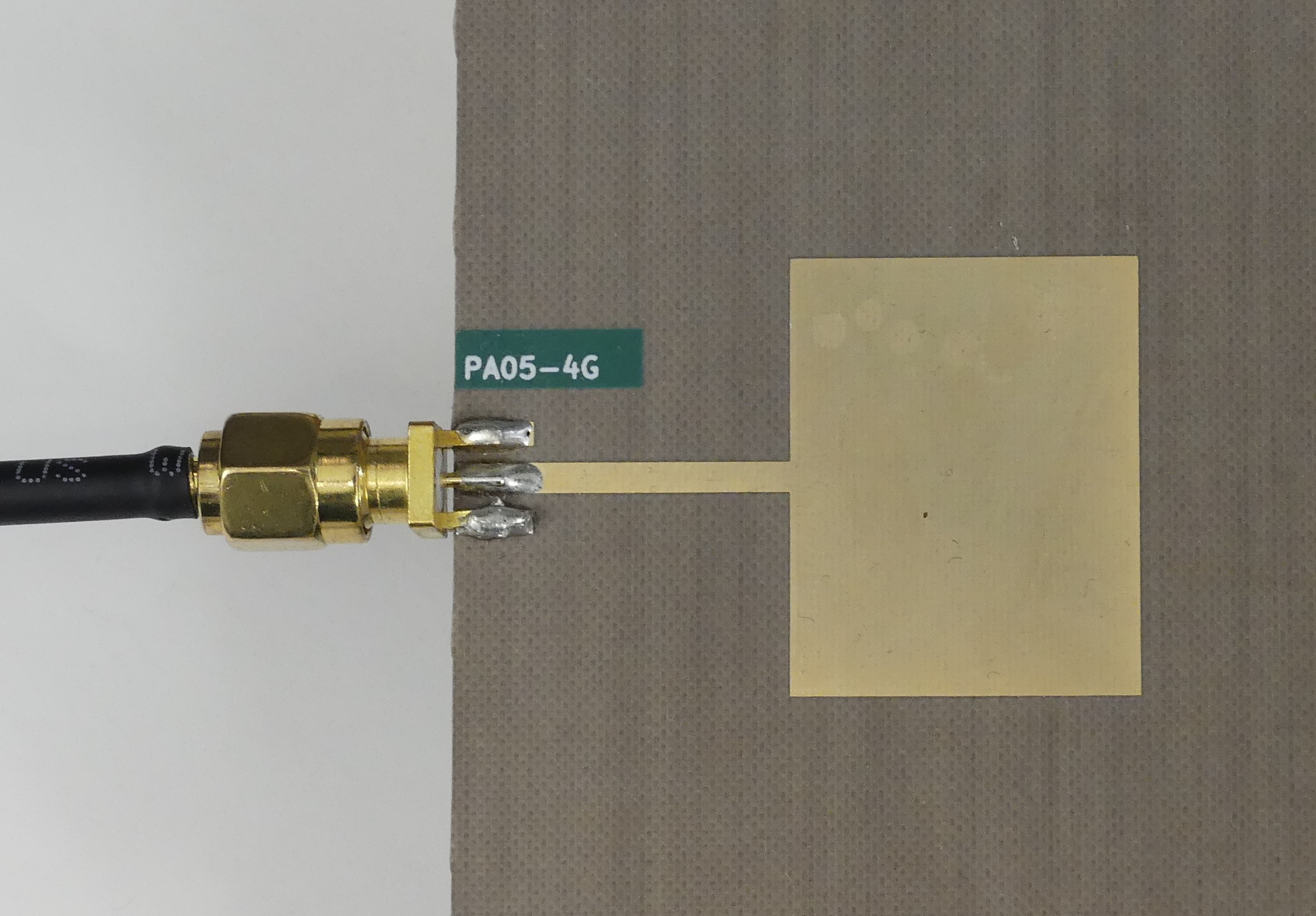
[PA05-4G]Dual-Band Patch Antenna #5 (~4 / 6.4 GHz)

Dual-band patch with modes near 4 GHz and 6.4 GHz. Both resonances within 1% of the RayRF prediction.

ctrl/shift+scroll: zoom  |  left or right drag: pan  |  double-click: reset
scroll to load
RayRF Studio
RayRF Studio
Mesh preview
Mesh preview
Hardware
Hardware

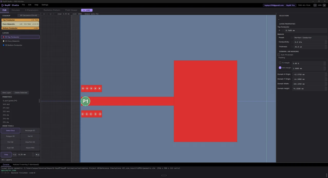
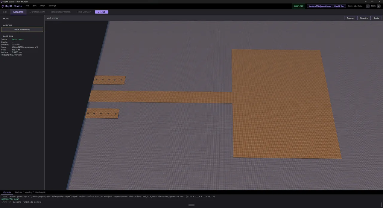
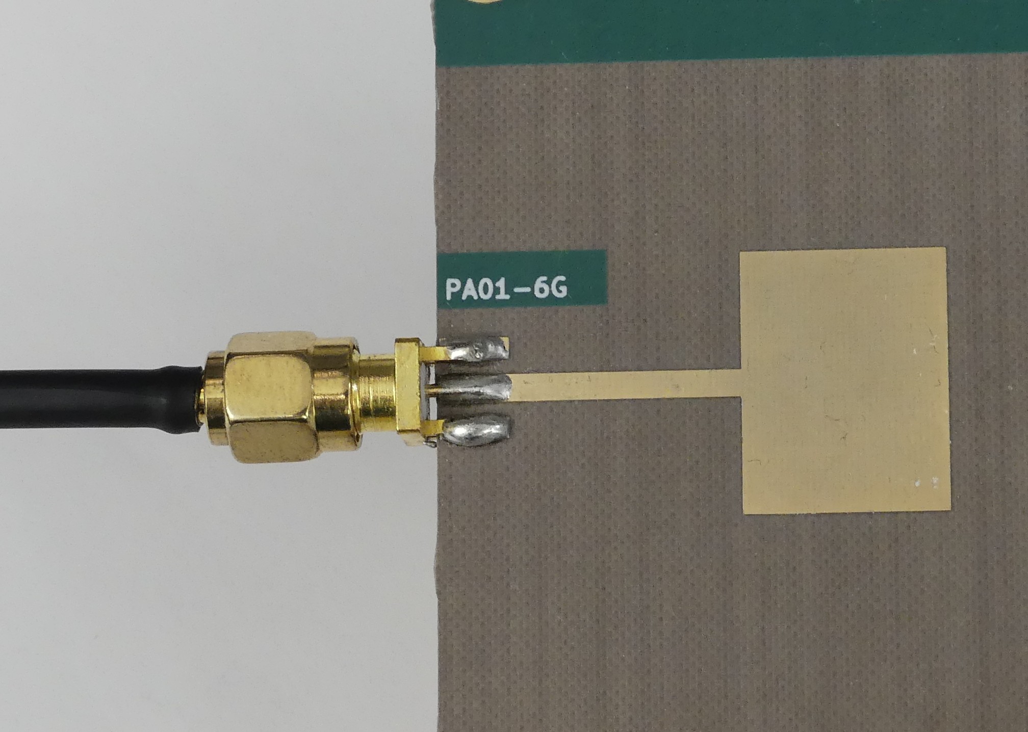
[PA01-6G]Patch Antenna #1, 6 GHz band

Single-resonance rectangular patch resonating near 6 GHz. Measured frequency matches RayRF within 1%.

ctrl/shift+scroll: zoom  |  left or right drag: pan  |  double-click: reset
scroll to load
RayRF Studio
RayRF Studio
Mesh preview
Mesh preview
Hardware
Hardware

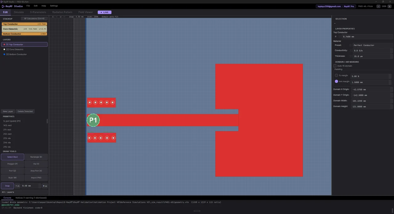
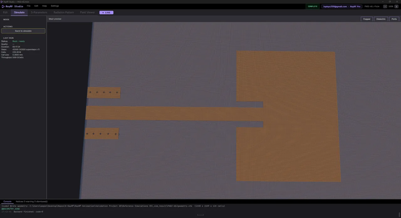
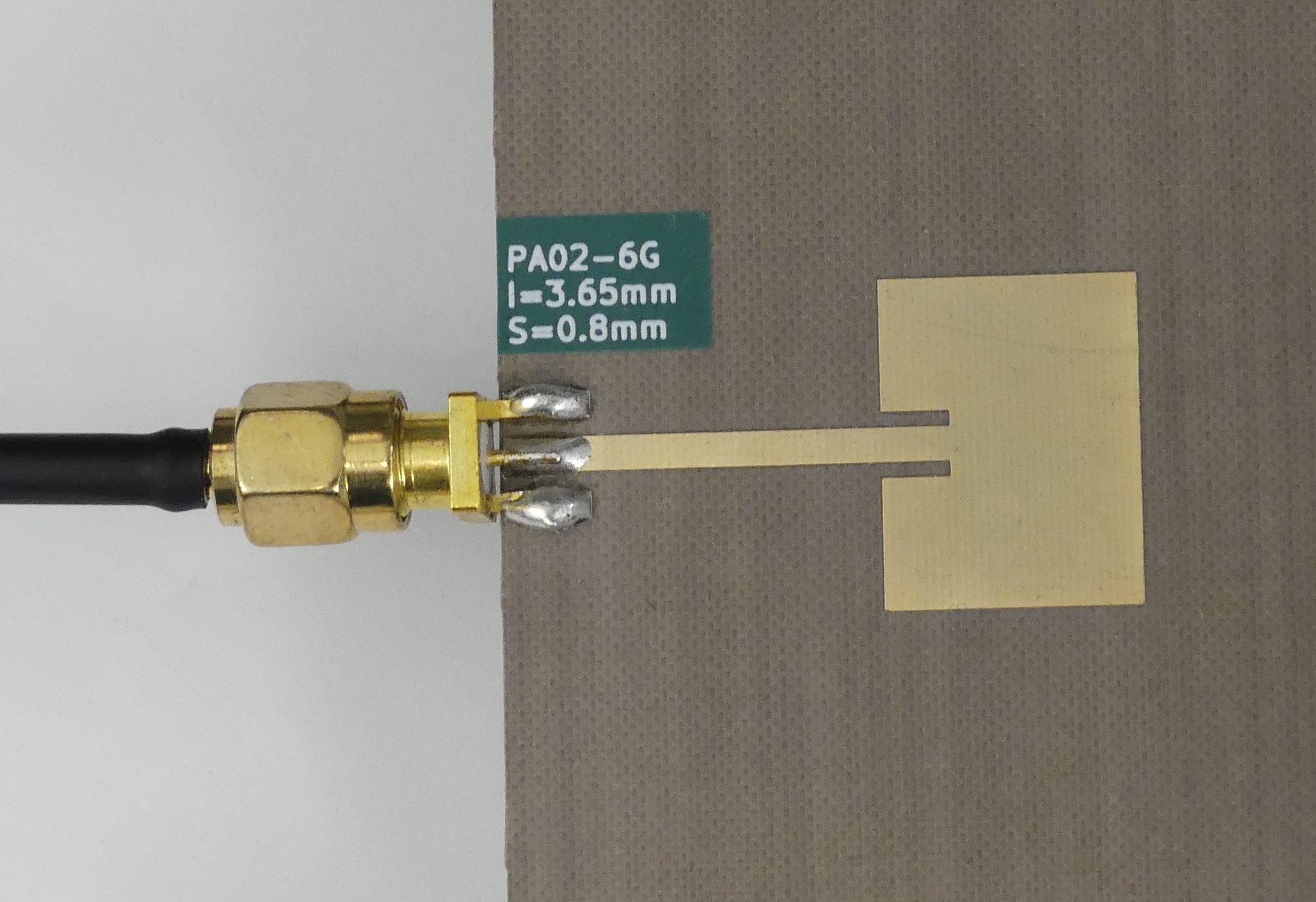
[PA02-6G]Patch Antenna #2, 6 GHz band

Inset variant in the same 6 GHz band, different feed geometry. Resonant frequency within 1%.

ctrl/shift+scroll: zoom  |  left or right drag: pan  |  double-click: reset
scroll to load
RayRF Studio
RayRF Studio
Mesh preview
Mesh preview
Hardware
Hardware

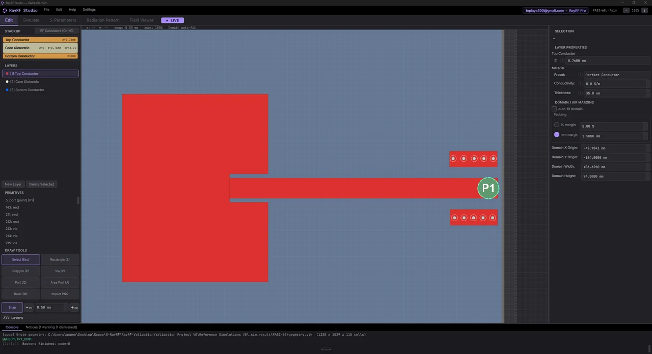
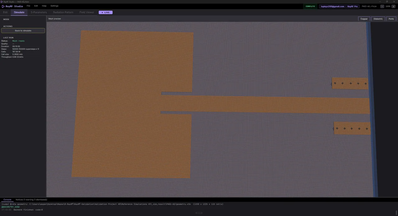
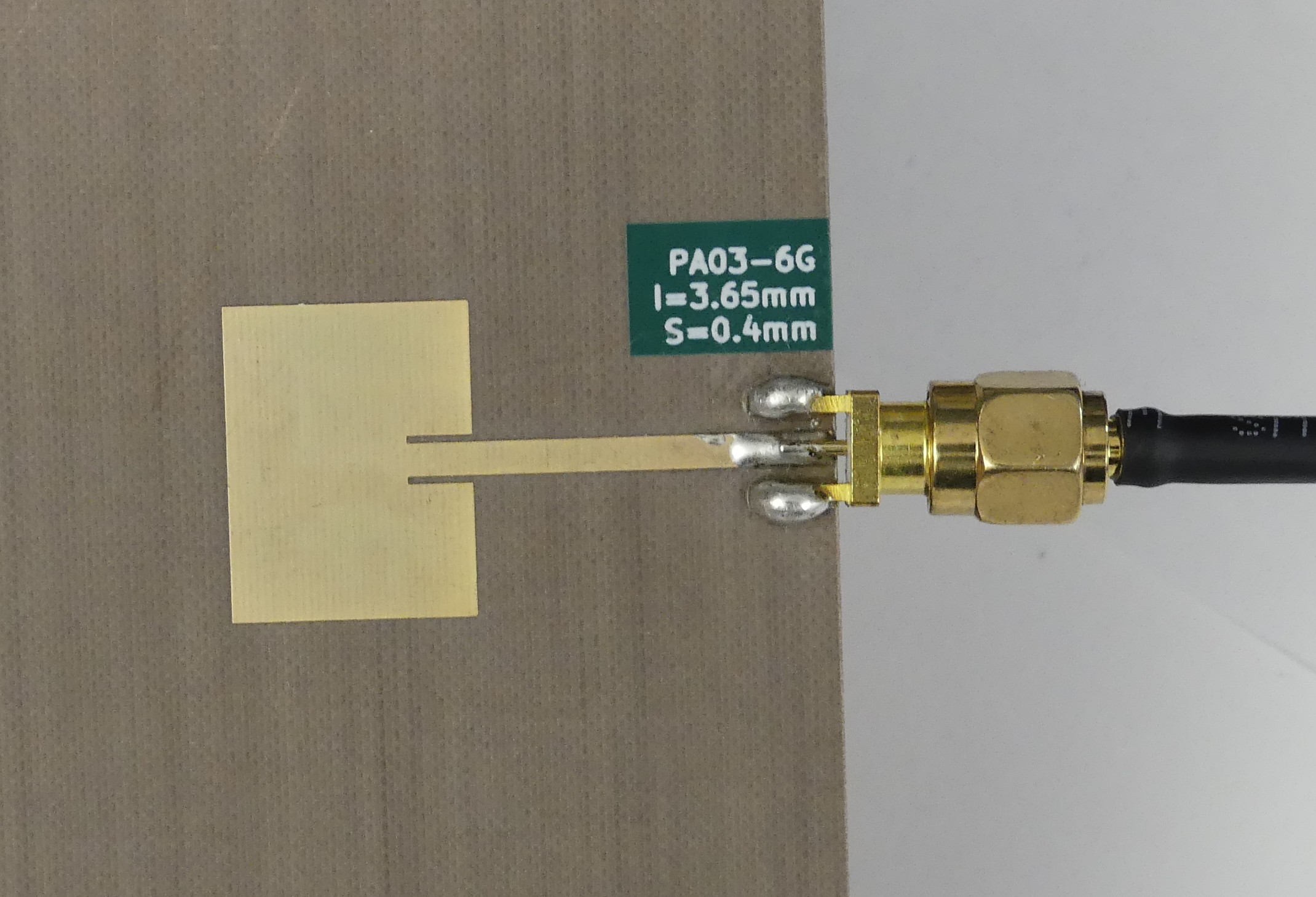
[PA03-6G]Patch Antenna #3, 6 GHz band

Different inset feed, resonant frequency within 1%.

ctrl/shift+scroll: zoom  |  left or right drag: pan  |  double-click: reset
scroll to load
RayRF Studio
RayRF Studio
Mesh preview
Mesh preview
Hardware
Hardware

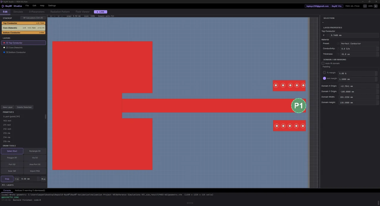
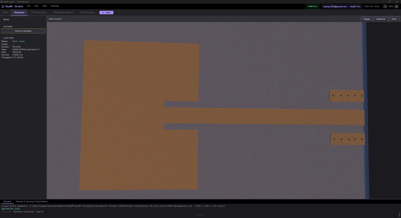
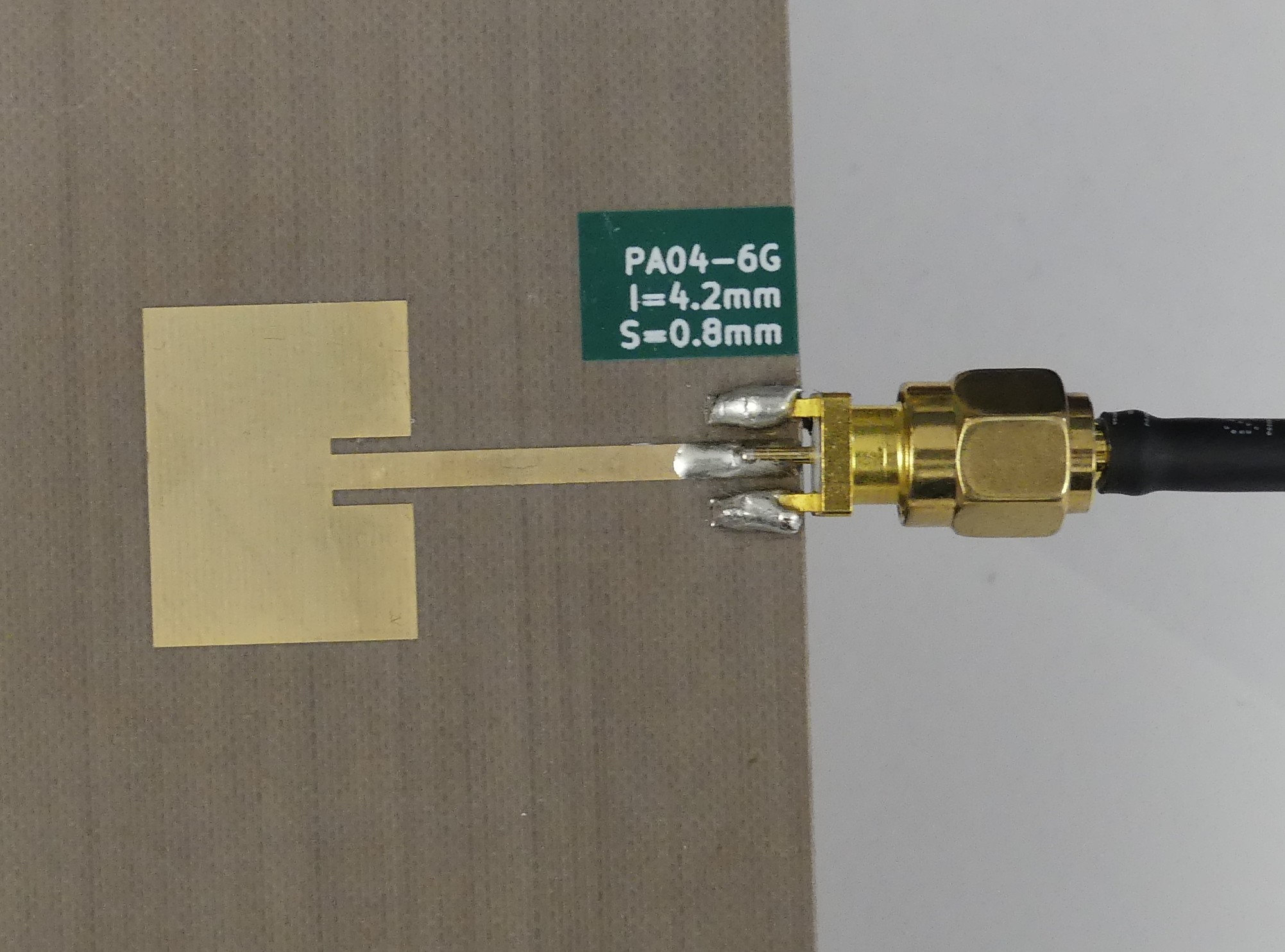
[PA04-6G]Patch Antenna #4, 6 GHz band

Final inset feed variantt in the same 6 GHz band. Resonant frequency within 1%.

ctrl/shift+scroll: zoom  |  left or right drag: pan  |  double-click: reset
scroll to load
RayRF Studio
RayRF Studio
Mesh preview
Mesh preview
Hardware
Hardware

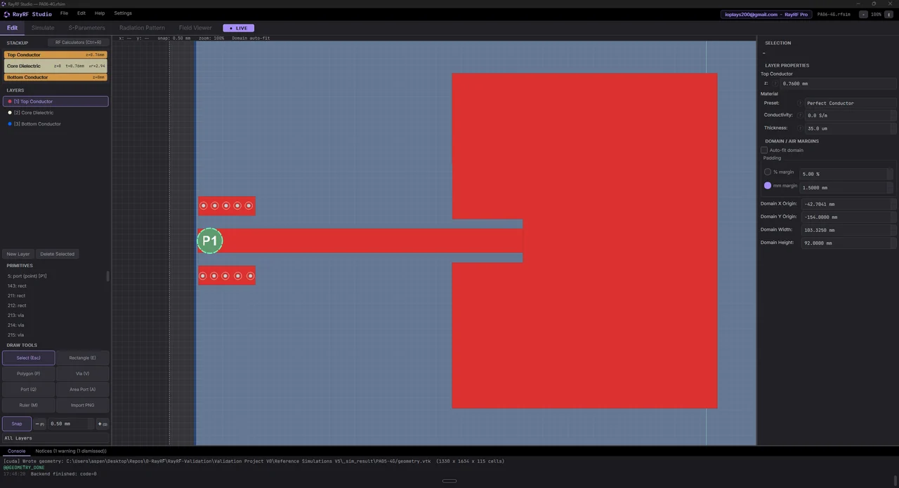
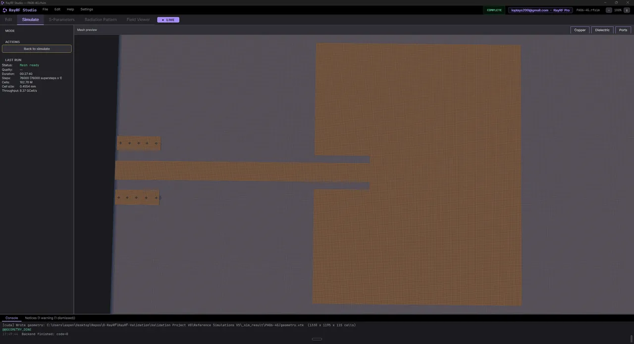
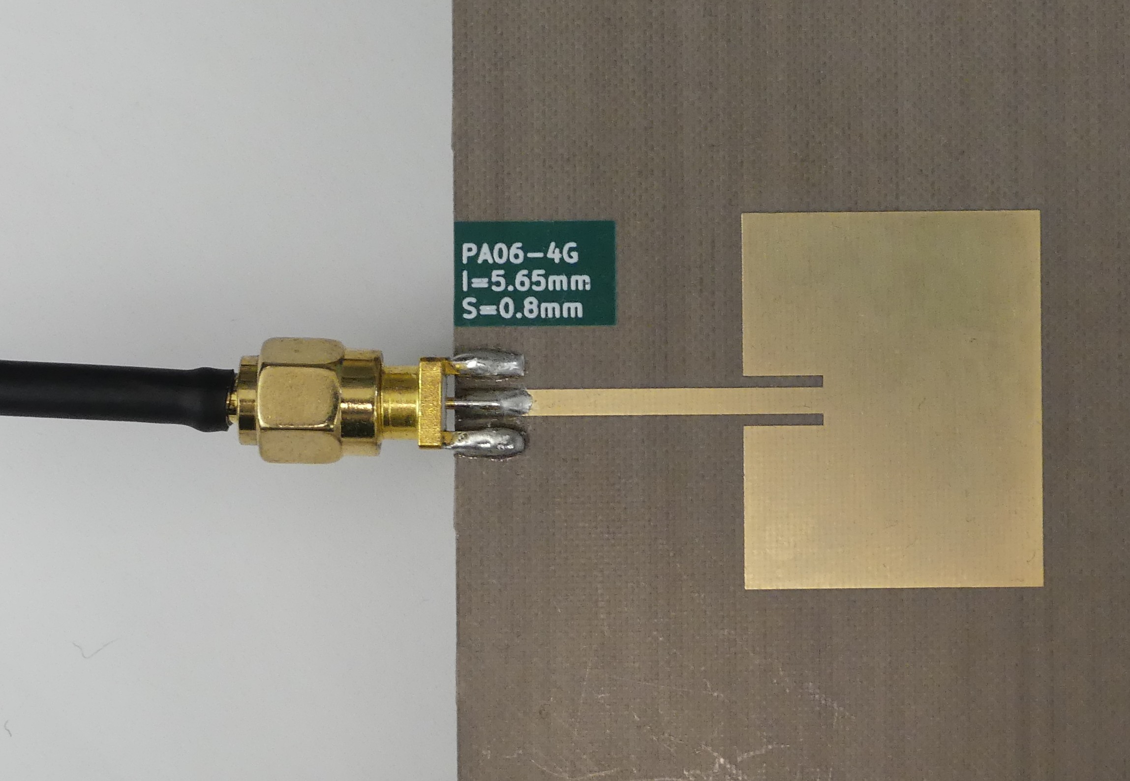
[PA06-4G]Dual-Band Patch Antenna #6 (~4 / 6.5 GHz)

Inset dual-band patch with modes near 4 GHz and 6.5 GHz. Both resonances within 1%, frequency, second resonance shows deeper "matching" due to lossless material idealization.

ctrl/shift+scroll: zoom  |  left or right drag: pan  |  double-click: reset
scroll to load
RayRF Studio
RayRF Studio
Mesh preview
Mesh preview
Hardware
Hardware

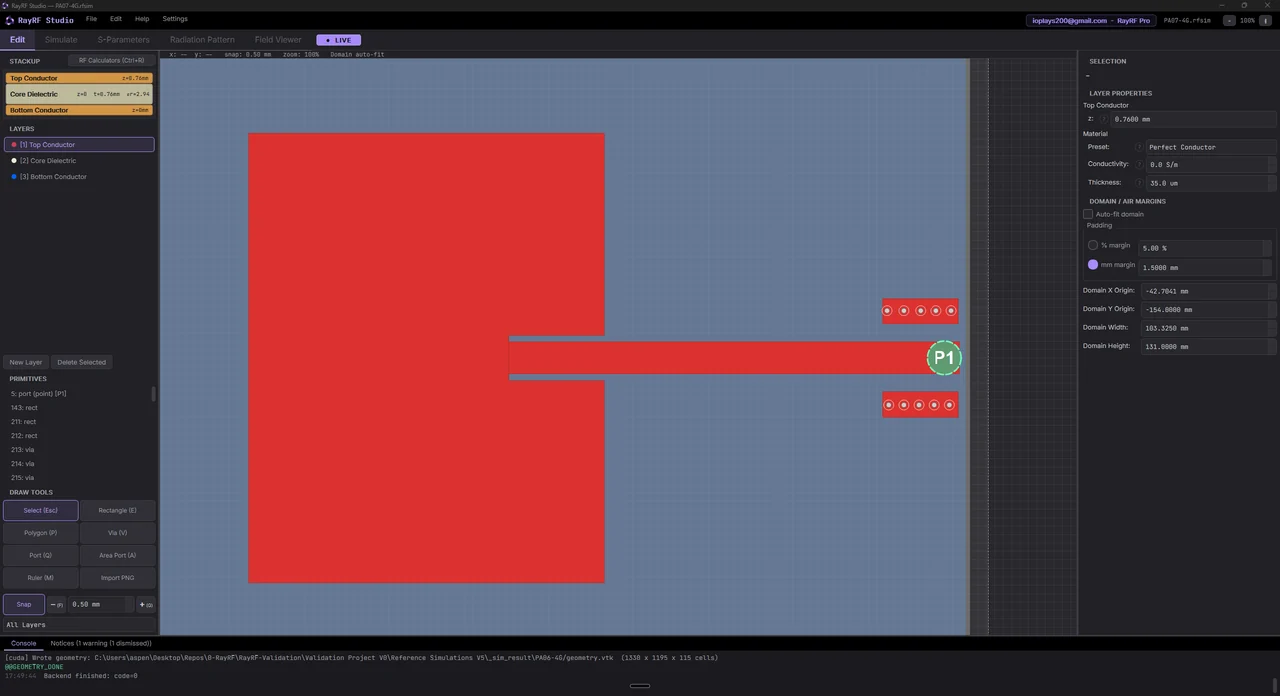
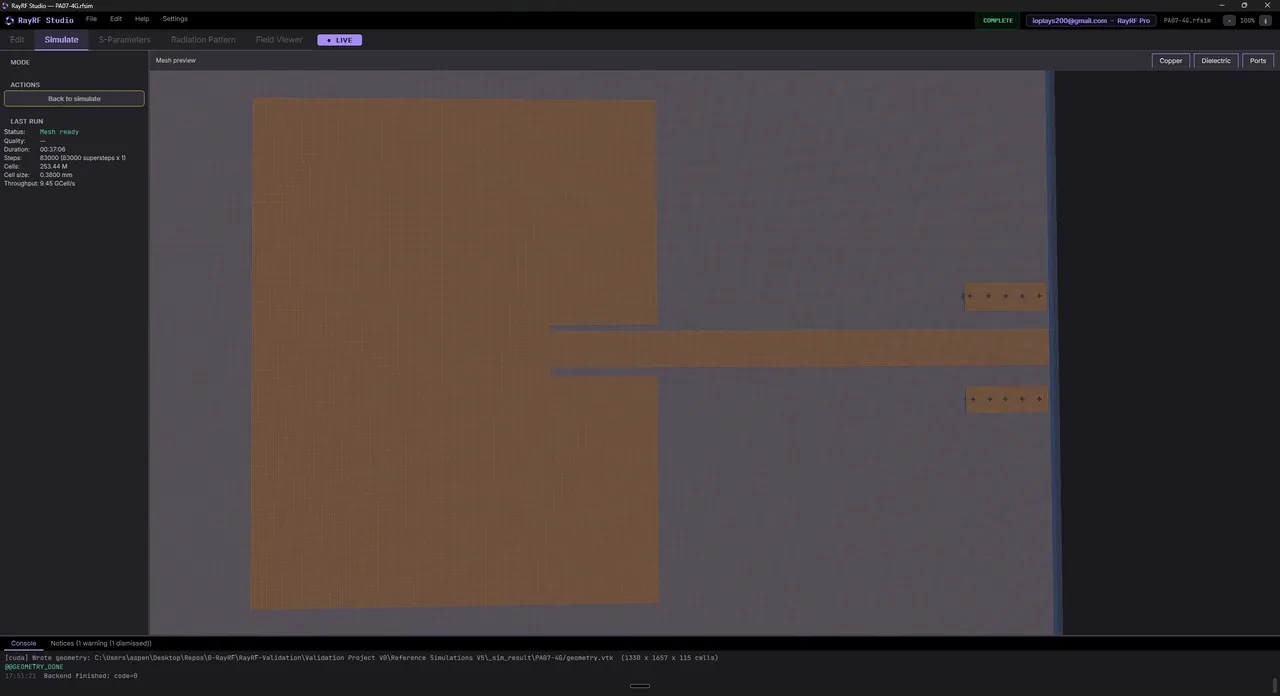
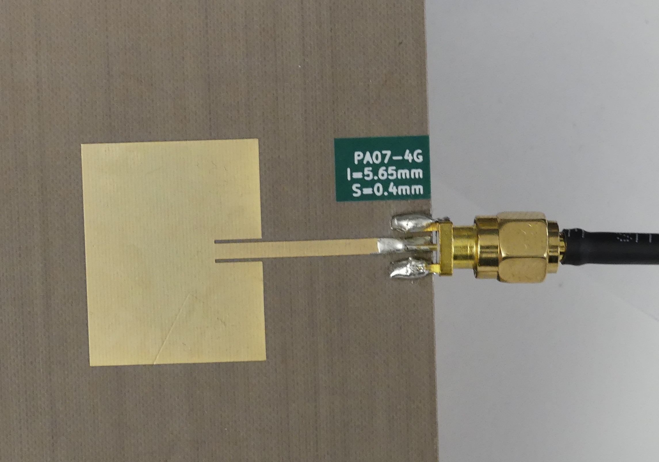
[PA07-4G]Dual-Band Patch Antenna #7 (~4 / 6.5 GHz)

Same 4G class patch with a different inset feed. Both resonances within 1%.

ctrl/shift+scroll: zoom  |  left or right drag: pan  |  double-click: reset
scroll to load
RayRF Studio
RayRF Studio
Mesh preview
Mesh preview
Hardware
Hardware

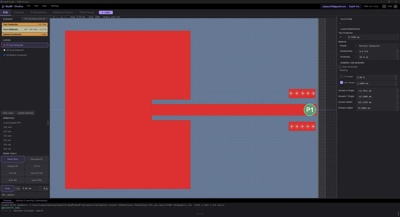
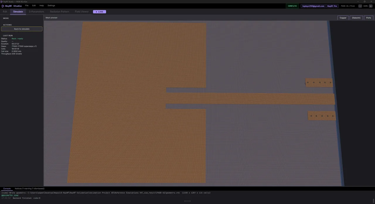
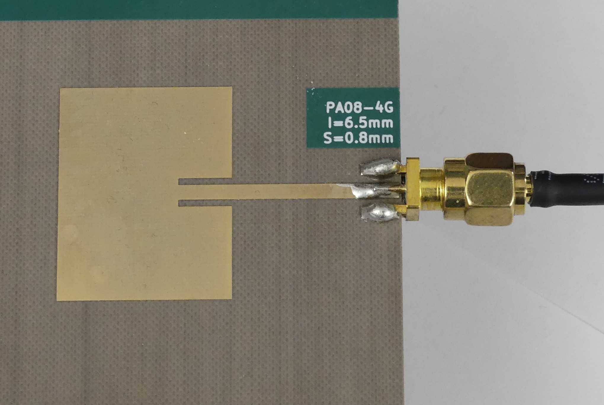
[PA08-4G]Dual-Band Patch Antenna #8 (~4 / 6.6 GHz)

Further inset feed variant of the 4G patch. Both resonances within 1%.

ctrl/shift+scroll: zoom  |  left or right drag: pan  |  double-click: reset
scroll to load
RayRF Studio
RayRF Studio
Mesh preview
Mesh preview
Hardware
Hardware

How the measurements were taken.

Measurements were taken using a LiteVNA64 warmed up for 24 hours to limit thermal drift during measurement. Short Open Load Through (SOLT) calibration was performed against high quality references, and redone five times at even intervals through the 10-hour session to characterize drift. Each device-under-test (DUT) was measured from 1 MHz to 8 GHz at 12,276 points with 5-trace averaging. The calibrations were applied by taking the median of all SOLT recordings.

S11 on 2-port systems was always measured with a precision 50 ohm load on the second port, which limits cable mismatch on the S21 side from corrupting S11. S21 is the VNA's direct through-measurement with no de-embedding, so the curve published here is what the same board gives you on your own bench.

Note: the LiteVNA64 is officially specified to 6.3 GHz, and although we believe our methodology of heavy averaging, multiple calibrations, and median processing greatly improves the reliability of the high-frequency results, treat anything above 6.3 GHz as reference only.
Stop waiting for your simulator.
Start designing at the speed of thought.